Different arm orientation
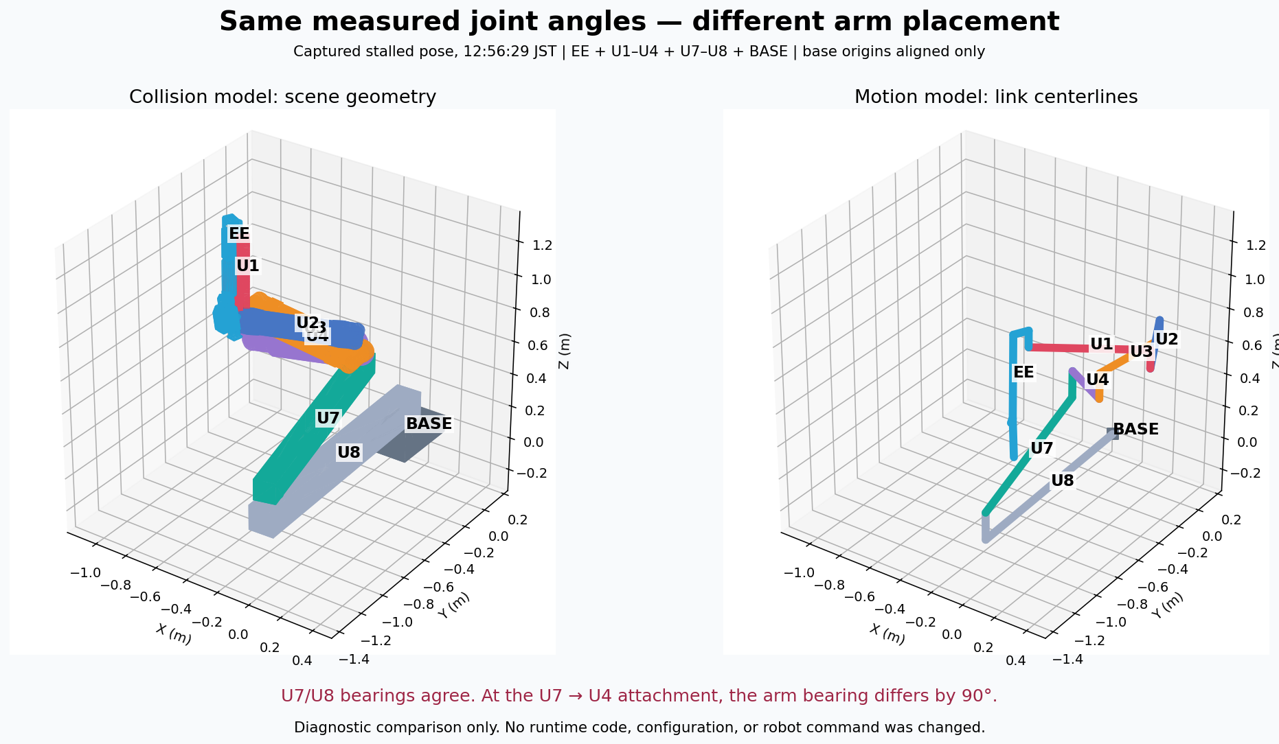
The disagreement starts where the shortened arm attaches to U7.
Recorded-pose investigation · 2 October 2026
The IK solver and collision checker receive the same joint angles, but place the shortened arm differently. That can make the software’s idea of “what is close” disagree with what you see on the robot.
The disagreement starts where the shortened arm attaches to U7.
Angle-based rules are used instead of a complete check between the two bodies.
The solver repeatedly times out at a capsule-clearance boundary.
The left image is what collision avoidance checks. The right is the motion model used by IK. Their base origins are aligned; the arm has not been rotated to make the drawings agree.
The logged U3 and U1 names trace to the correct scene objects and software motor slots. Correct names do not guarantee correct body placement.
U4 points a different way in the two models.
Bearing-only schematic at zero joint angles. Local origins aligned; dimensions and heights omitted.
The full scene connects U7 → U6 → U5 → U4. Your robot connects U7 → U4.
The collision model removes U6/U5 and reconnects U4, but keeps a local mounting transform that originally belonged under U5’s yaw. The motion model constructs its shorter chain separately.
Those two constructions disagree. U7/U8 bearings agree within 0.005°, while the first arm link differs by 89.9985°.
Which mounting orientation matches the physical robot. This audit proves the two software models disagree; it does not independently measure the hardware mounting.
“The checker reports this pair” and “these are the closest physical parts” are different claims.
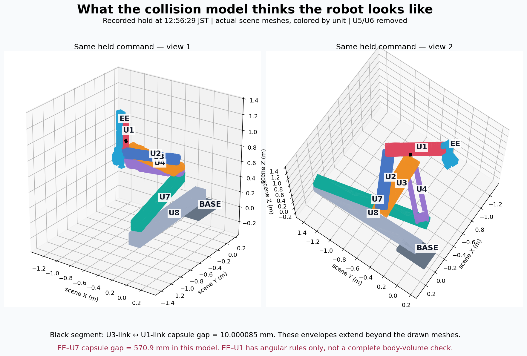
The collision model reports about 57 cm between its closest EE/U7 envelopes. Both the commanded and measured poses give a similar value. The 90° attachment disagreement is a reason not to treat that number as the robot’s actual clearance.
These adjacent bodies are excluded from the capsule checks. Two angular rules pass in the recorded pose, but they do not test every EE surface against every U1 surface.
The last accepted command sits at 10.000085 mm capsule clearance. The measured pose gives about 14.9 mm. These are model-envelope gaps, not measured metal-to-metal distances. Rotating the entire arm relative to U7 would preserve U3–U1’s relative separation.
| Scene shape | Parent joint | Motor identity | Wire slot |
|---|---|---|---|
| Unit3_link | FA_joint10 | UNIT_3 / PITCH | 9 |
| Unit1_link | FA_joint14 | UNIT_1 / PITCH | 13 |
Wire slots are zero-based and do not shift when units are absent. Incoming yaw ownership is preserved: U2 yaw moves U1’s body; U4 yaw moves U3’s body.
The existing rules use joint angles as an approximation of clearance. They do not calculate the full distance between the EE and U1 bodies.
The permitted minimum ranges from −20° to −12°, depending on U1 yaw.
This rule accepts either condition. When its yaw branch passes, this rule alone does not restrict EE pitch.
Starts at the recorded command, rounded to 0.1°. This is an explanation of the raw rules, not a robot control or a complete motion-safety verdict.
Passing these rules is not proof of body clearance. EE–U1’s complete shapes are not checked against each other. Motor limits and other collision checks still apply separately.
Let φ be U1 yaw’s wrapped angular distance from ±180°. At the recorded pose, φ ≈ 28.3°.
Rule 1 requires U1 pitch + allowed_downward_pitch(φ) ≥ 0. The allowance is interpolated from φ = [0, 100, 140, 180]° and allowance = [20, 20, 12, 12]°.
Rule 2 requires max(93° − φ, EE pitch + max(allowance(φ) + U1 pitch, −90°)) ≥ 0. Its allowance uses φ = [0, 93, 143, 180]° and values = [77, 77, 0, 0]°.
The planner also uses mechanical headroom of up to 2°, and validates the commanded joint segment. The explorer intentionally shows the underlying angular rules; it does not simulate all planner checks.
The log still gives a clear explanation of the software hold, even though the model’s physical accuracy now needs attention.
COMMAND was ON. The selected group was EE + U1–U4. Motors remained online and feedback was fresh.
Every tick returned a deadline hold. No new movement command was requested during this window.
Its proposed movements approach the 10 mm capsule-clearance limit. Numerical rounding can put a candidate just below the limit, while certifying the entire movement can consume the 35 ms calculation budget.
The next tick starts from the same accepted pose and repeats the problem.
Correcting the attachment geometry does not automatically solve this numerical stall. Keeping all distal bodies in the same rigid orientation relative to one another preserves U3–U1’s gap.
The inspection is complete enough to identify the model mismatch. A correction has not been deployed.
| Question | What the evidence establishes |
|---|---|
| Are U3 and U1 mislabeled? | No swapped index was found in the scene-object → wire-slot → protocol identity mapping. |
| Do the models agree? | No. With the same joint angles, the partial arm differs in bearing by about 90° at the U7 attachment. The full U1–U6 comparison agrees in bearing. |
| Which model matches hardware? | Not independently qualified by this audit. The reported EE–U7 proximity is consistent with the motion-model drawing. |
| Is EE–U1 fully covered? | No complete volume test. The two angular rules pass in the captured pose. |
| Was physical contact proved? | No. These logs and calculations describe modeled envelopes and motor angles, not measured surface contact. |
Confirm the physical mounting orientation, reconcile the partial-assembly transforms, and check agreement for every supported assembly.
Distinguish the intended attachment region from other EE/U1 surfaces that can collide. Blanket exclusion of adjacent bodies leaves a gap in coverage.
Account for command rounding and reserve time for smaller, fully checked steps. Keep the collision threshold enforced.
Deployed source: baf3caf6e01fa854cb6b782cf06c8b2d87e3a75b. Recording: user-run-035455, 2 October 2026.
The independent scene-hierarchy evaluator agrees with the collision model’s transforms to approximately 5 × 10⁻¹⁶. The bearing mismatch reproduces with U1-only through U1–U5 assemblies containing U7/U8, and with the recorded U1–U4 pose. This is not a disagreement created by the drawing.
Three focused existing checks passed: scene export identity, zero-pose scene transforms, and all 19 UT targets through a local gRPC boundary. They do not test motion-versus-collision frame agreement on shortened chains.